Setup
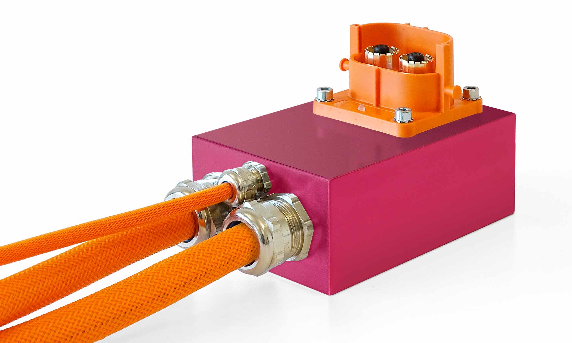
- HV-BREAKOUT BOX HIGH POWER
- HV-BREAKOUT BOX LOW POWER
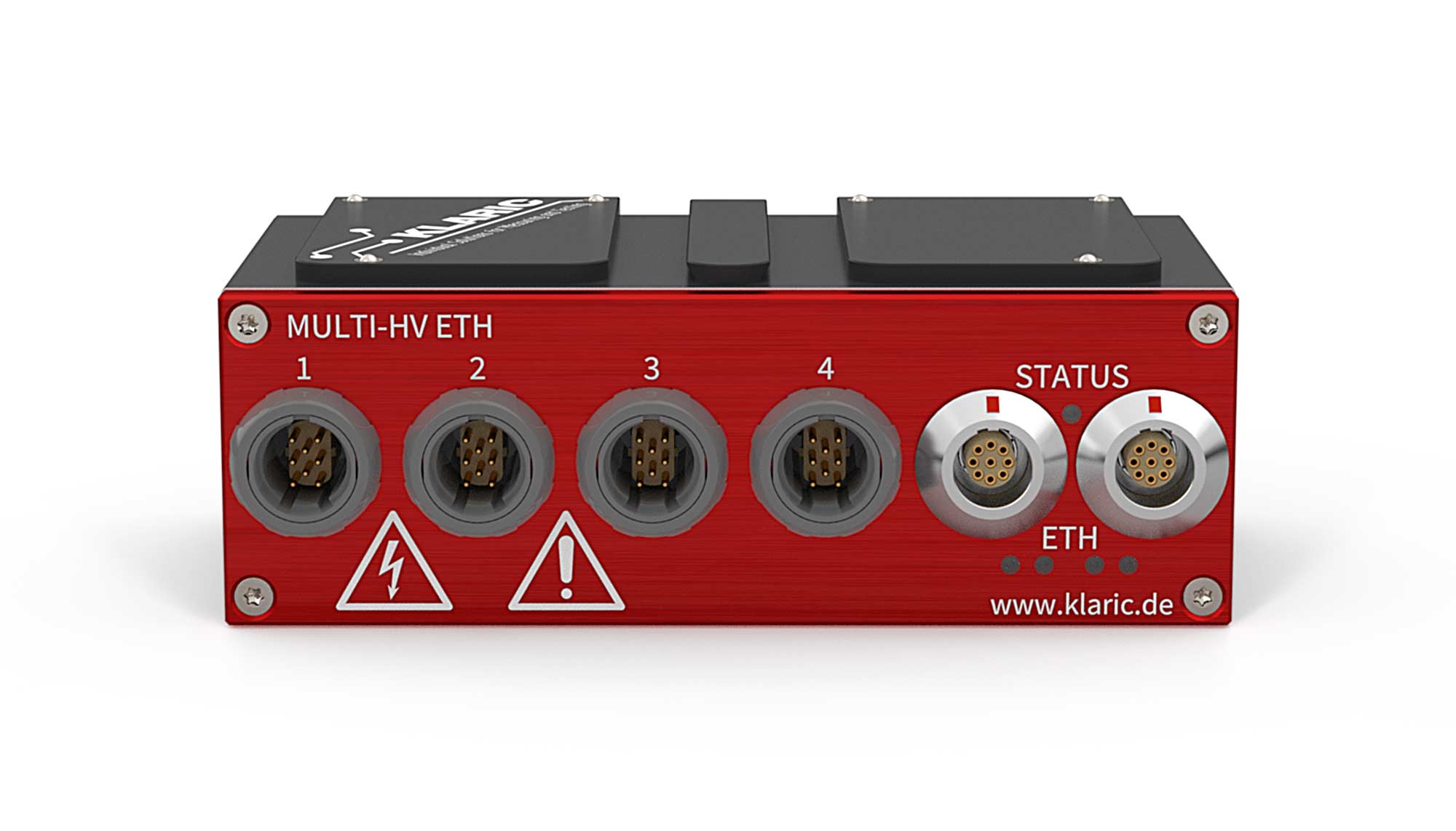
- MULTI HV ETH
With the further development and associated complexity of high-voltage vehicle electrical systems, the number of measuring points is also increasing. Fast integration of sensors and exact measured values are therefore all the more important for successful development.
The high-voltage measuring technology from KLARIC helps to achieve the goals of development and quality departments and thus to optimize the development cycle in terms of time.
Carrying out the measurement
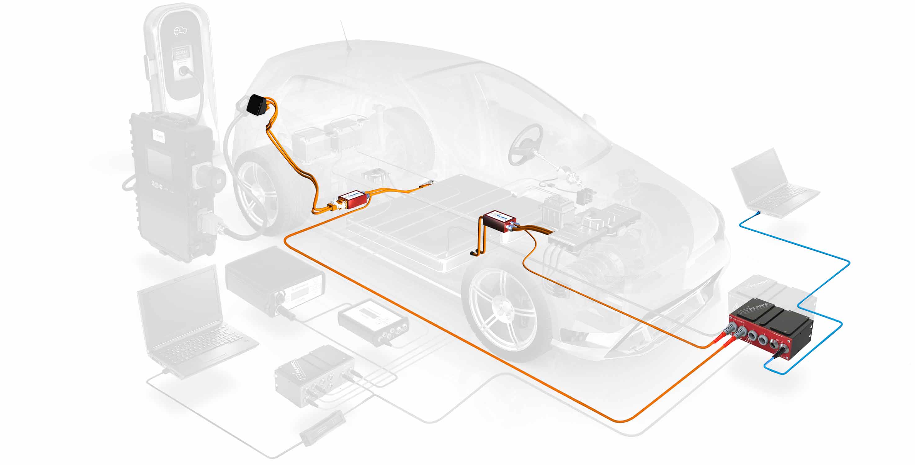
First, the measurement technology must be installed in the vehicle. The HV breakout boxes with original connectors are ideal for this. The breakout box is equipped with a KLARIC HV-P-PROBE and then equipped with identical HV connectors as the test vehicle. In order to find the optimal installation space, the conditions must first be clarified.
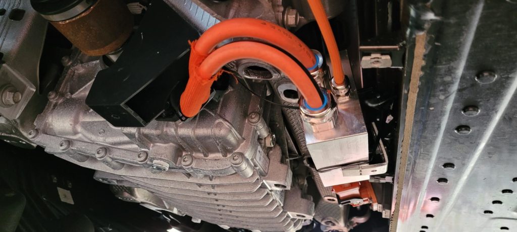
Installation of a HV breakout box
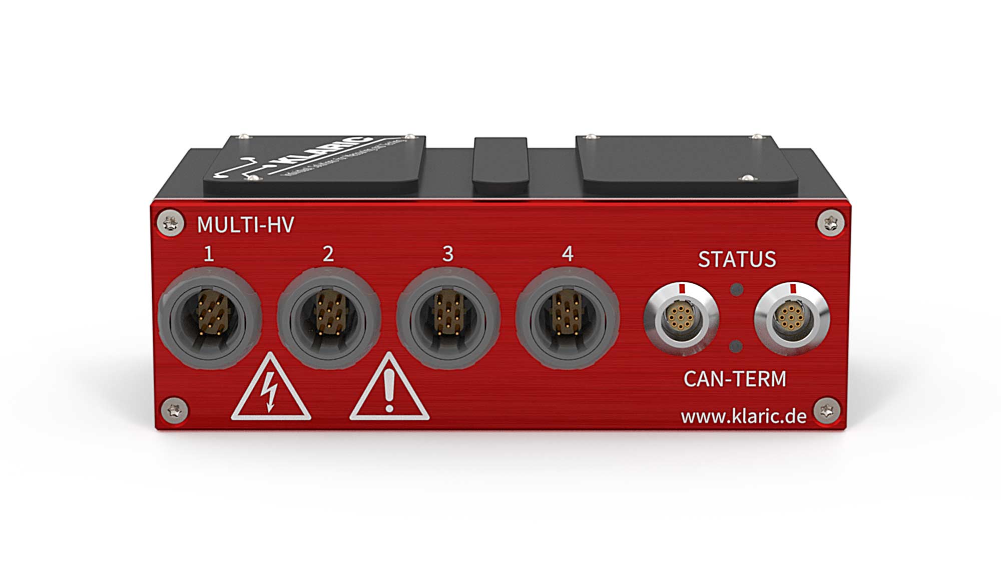
For this purpose, a space analysis is carried out. The measuring adapters can be installed in the vehicle using a CAD replacement model to clearly clarify the installation capability. In order to be able to guarantee the optimal properties with regard to the resolution of the measurement and the electrical load of the HV-P-PROBE, the expected nominal current consumed by the HV consumer must be known. After the measuring adapter has been installed by trained personnel, it must be connected to the MULTI HV. The HV measurement module is supplied with voltage and set up after it is connected to the HV breakout box. For this purpose, the measuring points are configured and named in the Klari toolbox. After the measurement module has been connected to a CAN/Ethernet logger or interface for data acquisition, the measurement can be started.
Evaluation of the measurement
The measured values can be recorded using a CAN interface or logger or data acquisition system via any Ethernet protocol. If the CAN bus is used, vehicle data can be recorded parallel to the measurement data.
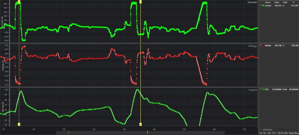
Evaluation of the measurement data
This simplifies the correlation between consumption and recuperation in the event of negative vehicle acceleration. The measurement data provide information on the efficiency of the drive and the HV consumers, which convert energy from the traction battery through the electric air conditioning compressor (ECC) or the electric auxiliary heater (HV-PTC).
