| | | | | | | | | | | | | |
|---|
| Module | Input | | | | Measurements | | | | Output | | Specials | | |
| Inputs | Channel | ADCs | Max.Fs | I | U | I+U | T | ETH | CAN | Dyn. sampling rate | Autorange | Power |
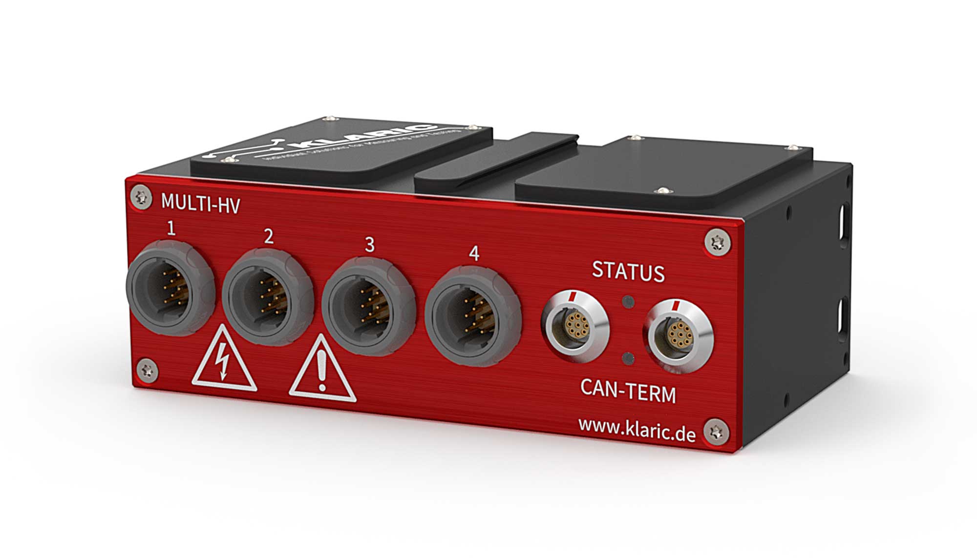
| MULTI-HV UIT | 4 | 8 | 8 | 8 kHz | √ | √ | √ | √ | - | √ | √ | √ | √ |
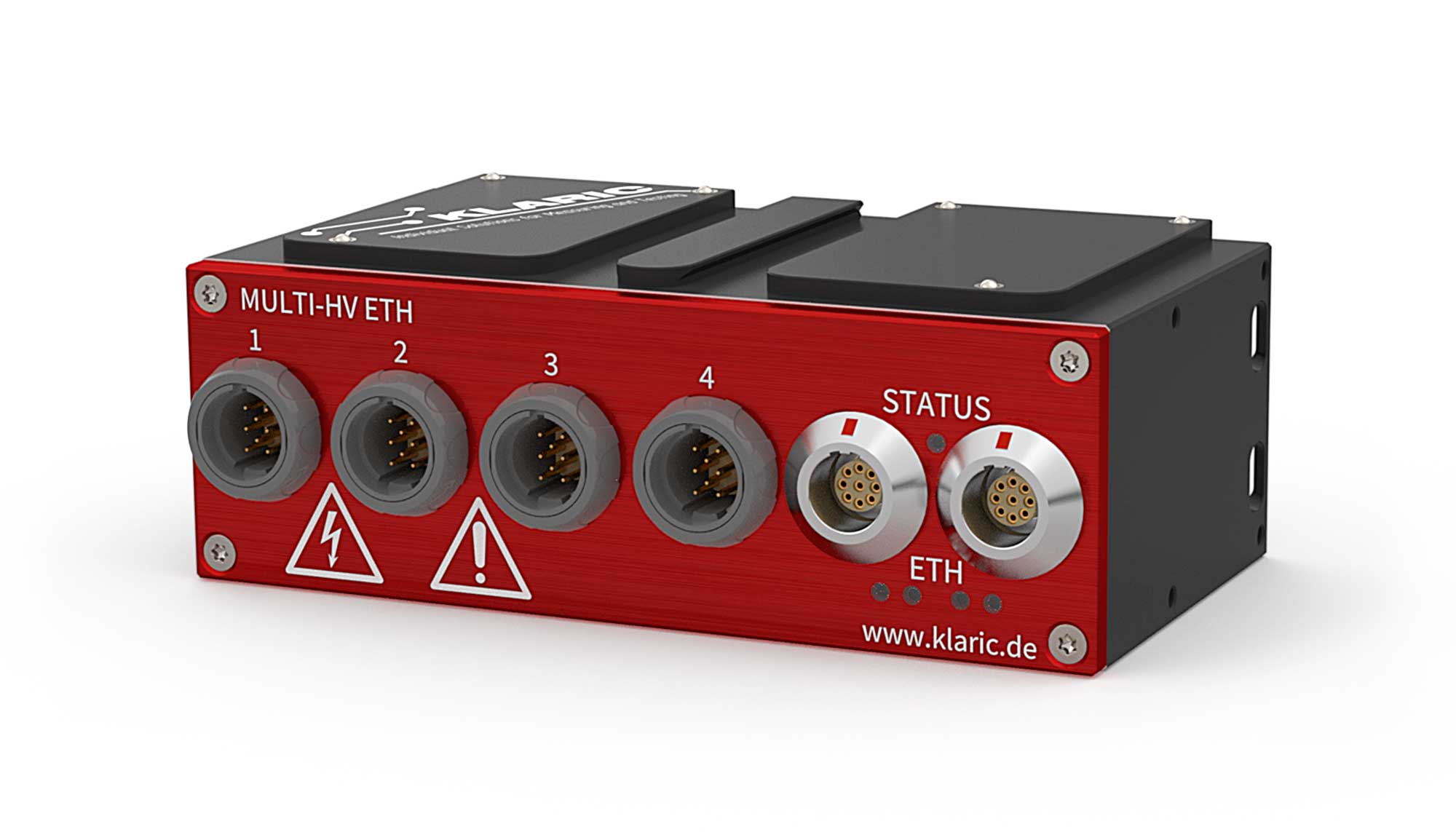
| MULTI-HV UIT ETH | 4 | 8 | 8 | 8 kHz | √ | √ | √ | √ | √ | - | √ | √ | √ |
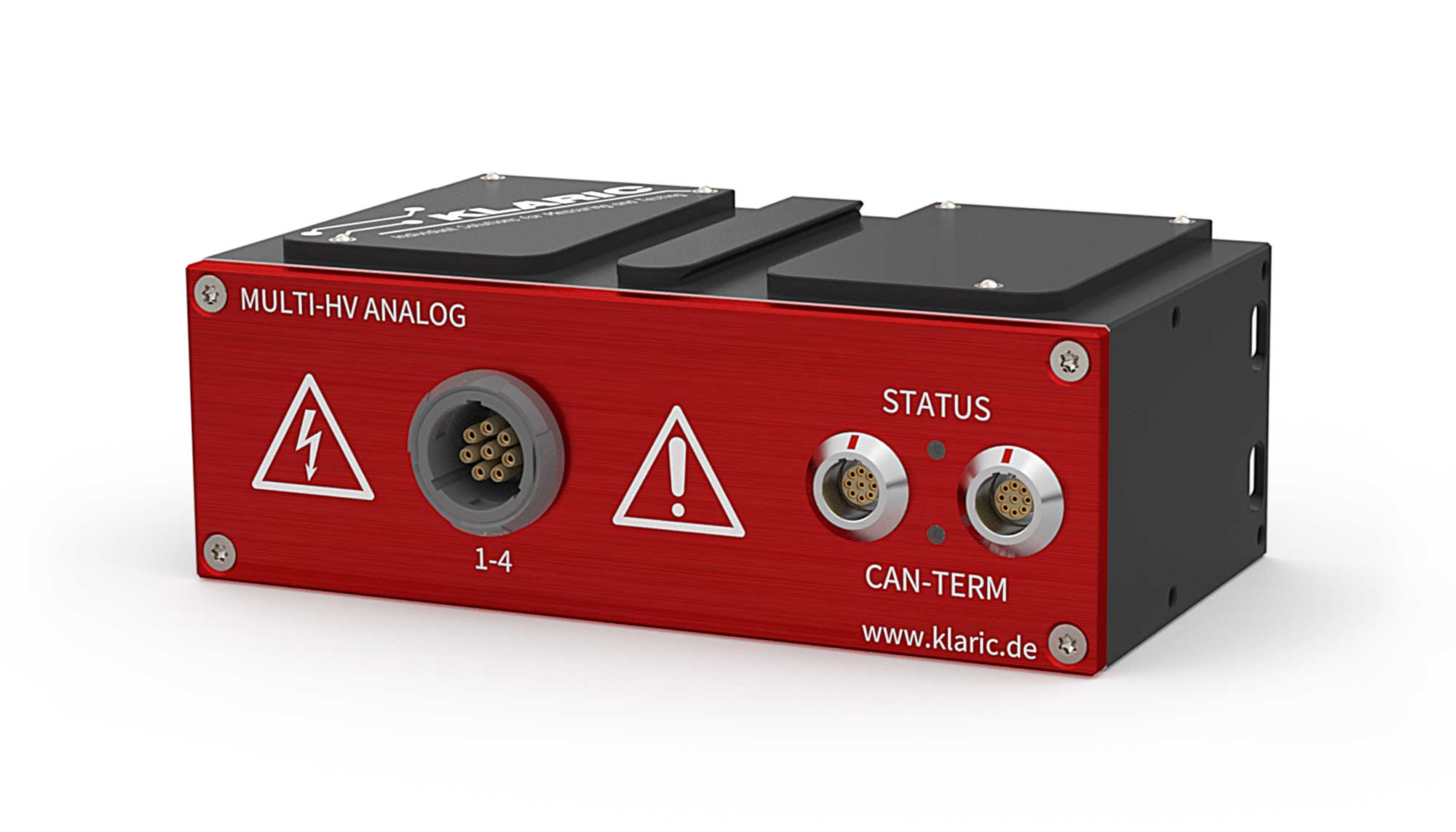
| MULTI-HV ANALOG | 1 | 4 | 4 | 8 kHz | - | √ | - | - | - | √ | √ | √ | - |
| MULTI-HV ANALOG ETH | 1 | 4 | 4 | 8 kHz | - | √ | - | - | √ | - | √ | √ | - |
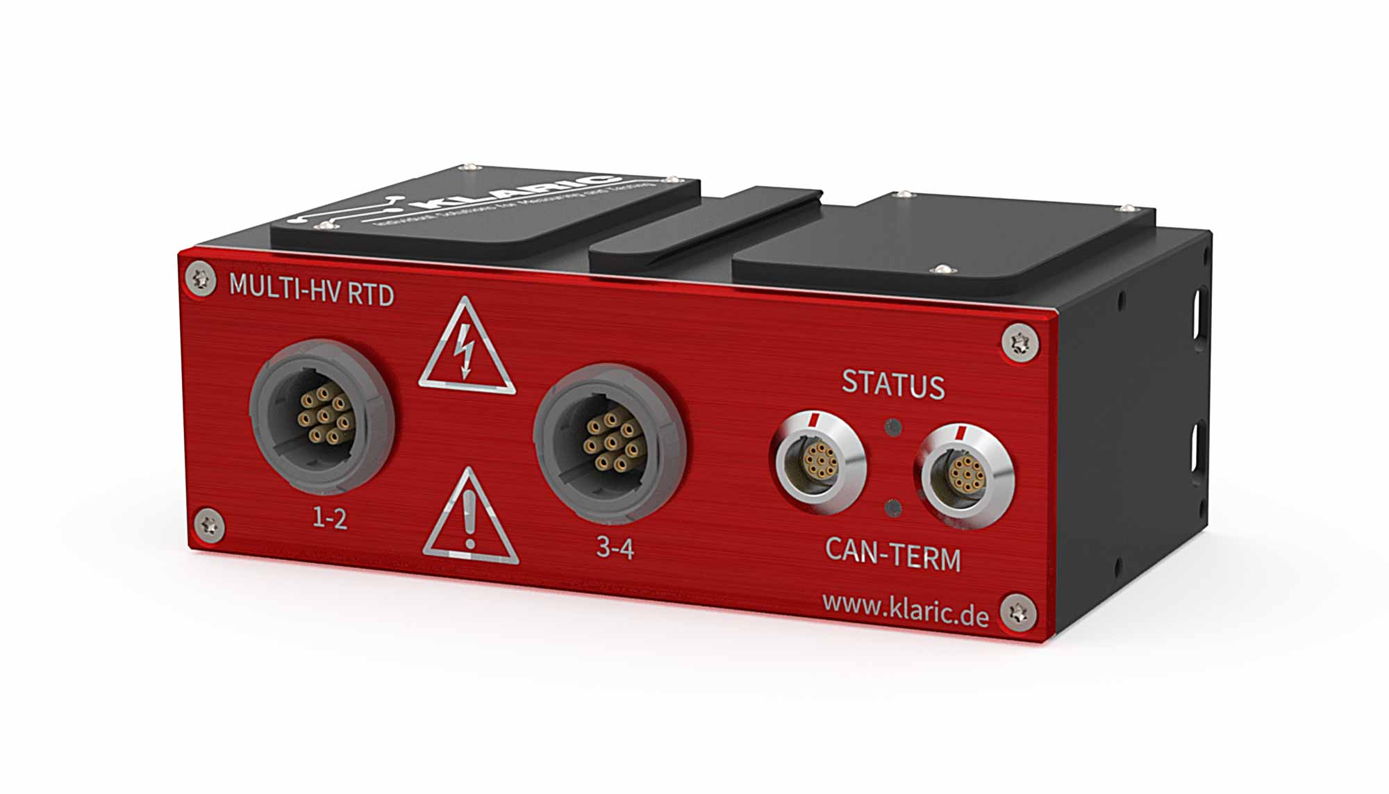
| MULTI-HV RTD | 2 | 4 | 4 | 8 kHz | - | - | - | √ | - | √ | √ | √ | - |
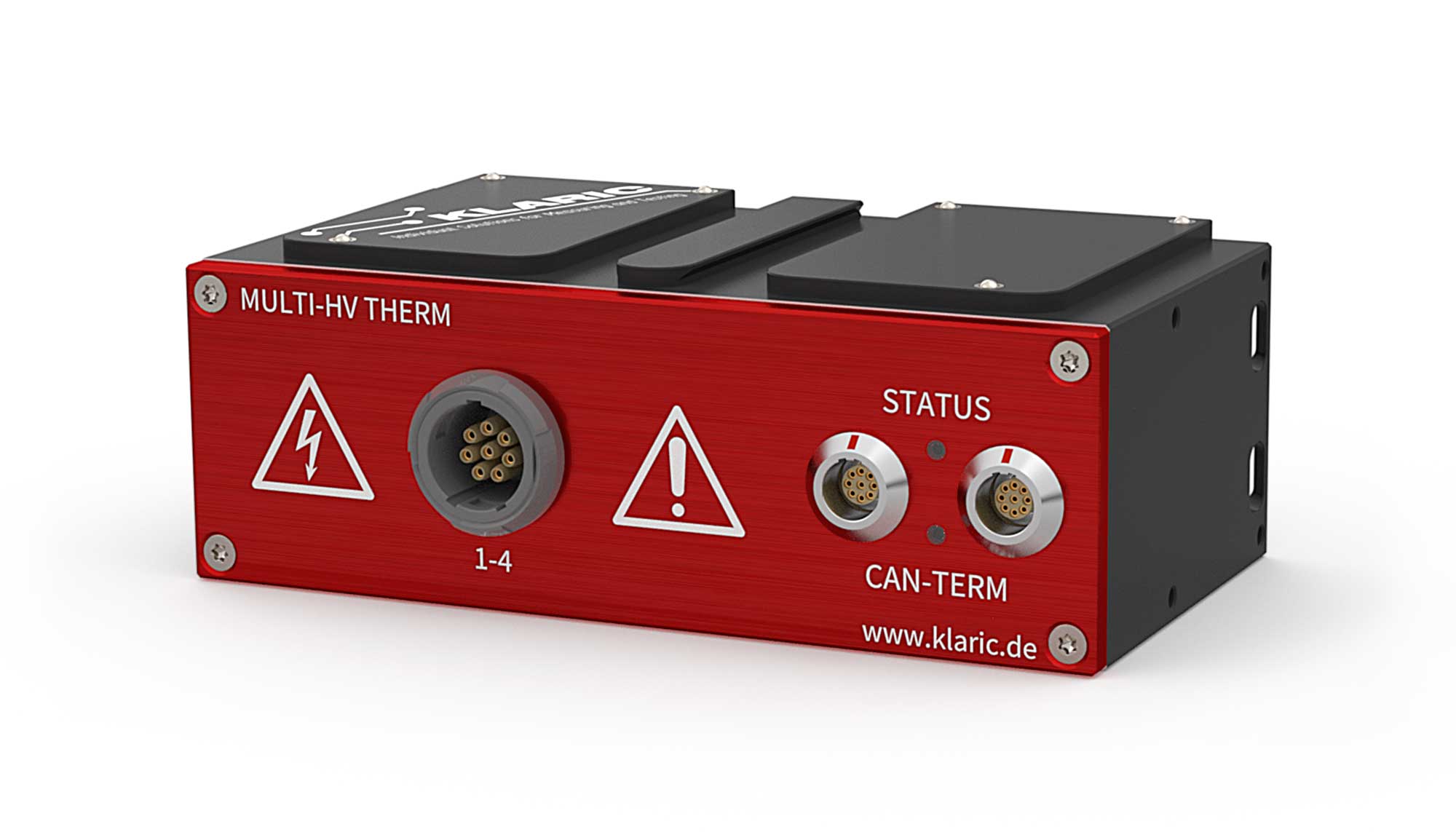
| MULTI-HV THERM | 1 | 4 | 4 | 8 kHz | - | - | - | √ | - | √ | √ | √ | - |
The modules allow direct connection of all typical signals such as voltage, current and temperature. The digitized measurement signals are available at the output as a CAN message or via XCP-on-Ethernet and can be read in or recorded by any measurement, automation or control system with a CAN interface.
In addition, the appropriate HV sensors and HV breakout boxes are available, with which a clearly defined and safe interface is established between the measuring point and a fully standardized and personnel-safe part of the installation, which is equipped with REDEL connectors towards the measuring technology. This allows Klaric to offer complete solutions from a single source.