Setup
MULTI-4/MULT-8 (formerly KLARI-FUSE 3)
HP-PROBE
Implementation
Connecting the probes and measurement modules
Connecting the measurement modules via the CAN interface
Performing the measurement
Due to the increasing number of electrical and electronic consumers in vehicles, there is a need to reduce CO2 emissions and fuel consumption by increasing the efficiency of electrical and electronic systems. To achieve this goal in the long term, currents, voltages, and temperatures must be measured and validated at power-intensive vehicle components such as electric heaters, pumps, and headlights. In vehicles with a 48V electrical system, relevant components include the DC/DC converter, the electric motor, and the 48V battery itself, as extremely high power levels occur here for short periods. The following describes some examples of measurements on power-intensive components.
During recuperation, when the vehicle brakes, energy is recovered and not converted into heat by being fed back into the battery. However, voltages, currents, and power levels must also be measured and validated for the aforementioned components during the development and testing phases. With the new measurement modules, calculated values such as charge/discharge and total energy balance, power, and energy can be calculated online during current and voltage measurements and output via the desired interface. Early detection of fault currents or excessive currents is essential, but implementing this is a significant challenge. High-resolution measurement technology for extremely wide current, voltage, and temperature ranges helps test and development engineers successfully meet this challenge.
For energy and battery management, voltages and currents of the overall system as well as at individual loads must be measured. By simultaneously measuring current and voltage with a single HP combination probe, only one measurement input is required in conjunction with the MULTI-4/MULTI-8, as two synchronously sampling analog-to-digital converters are available per measurement input. Current is measured via a low-resistance shunt, and voltage via a voltage divider. The unique auto-range function enables the measurement of quiescent and operating currents and voltages with the highest possible resolution. No pre-selection of the measurement range is required during setup, significantly reducing setup time. The table below shows the measurement ranges, resolutions of the analog-to-digital converters, and those of a 1 mΩ and a 200 µΩ high-performance probe:
The maximum continuous current of the 1 mΩ probe is 120 A at the maximum achievable resolution of 300 µA/bit with a gain of 100, while the resolution under full load is 7 mA/bit.
The calibration values of the shunt and the voltage divider are stored in the probe and are automatically read when the probe is connected to the measurement module and processed during data acquisition. The shunt's calibration value is the actual resistance value measured on the test bench. The output interface for the measurement data is freely configurable, offering two CAN interfaces and one 100 Mbit/s Ethernet interface with XCP-on-Ethernet or the KlaricServer. The DBC or A2L file is automatically generated with a single mouse click in the KlariToolBox, including all connected samples. The "plug and measure" principle significantly reduces setup time. Online calculation of power, charging, discharging, and total balance ensures that all necessary values are calculated and output during the measurement, enabling particularly simple evaluation without the need for numerous additional calculations afterward.
Measurement Evaluation
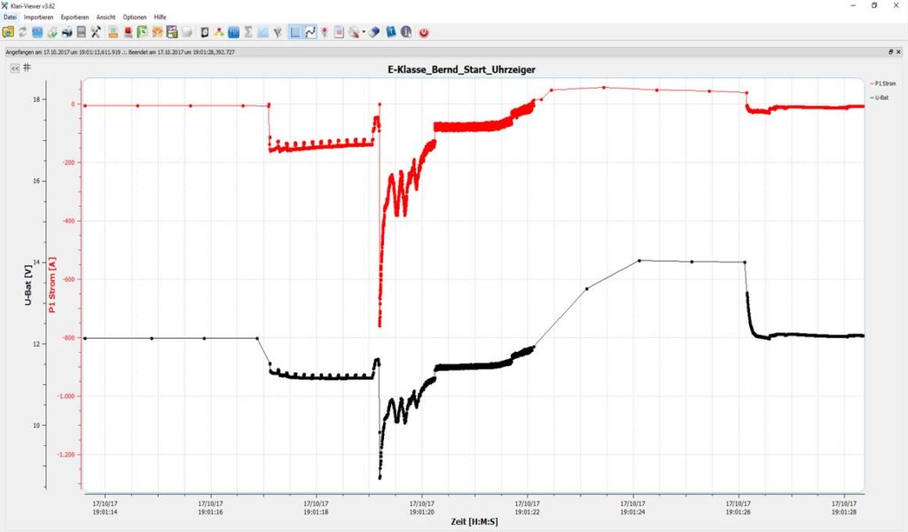
The following diagram shows the starting process of a conventional 6-cylinder diesel vehicle with a 12V electrical system, recorded with a KLARI-CORD 5 during a long-term measurement. The measured peak current during starting is -757 A, with the electrical system voltage dropping to 8.7 V. These values also depend on the selected sampling rate. Since power and therefore current have increased rapidly in conventional 12V electrical systems, more and more models will be equipped with 48V systems in the future.
RPM = 8.7 V Imax = -757 A
Upon closer inspection, it becomes apparent that the sampling rate is not constant, but dynamic. In all new measurement modules, a threshold for current, voltage, or temperature can be set, at which point the sampling rate changes. This means that, for example, quiescent current measurements are taken at only one hertz. If the measured value now exceeds the set threshold, the peak current and the signal waveform can be analyzed, potentially allowing conclusions to be drawn about the cause. Upon closer inspection, it becomes apparent that the sampling rate is not constant, but dynamic. In all new measurement modules, a threshold for current, voltage, or temperature can be set, at which point the sampling rate changes. This means that, for example, quiescent current measurements are taken at only one hertz. If the measured value now exceeds the set threshold, the peak current and the signal waveform can be analyzed, potentially allowing conclusions to be drawn about the cause. When measuring the current and voltage of the electromechanical steering system, the dynamic sampling rate significantly reduces the amount of data to be analyzed, as continuous recording is possible during test drives without having to switch the measuring equipment on or off. This applies in principle to all measurement tasks, including the DC/DC converter, where the currents are almost static.